Manufacturing the Crane.
The material I used for building the crane are aluminium square profiles from the DIY store, they are easy to get, cheap and light.
For the sides I took 1 mm plates aluminium, in these plates are also the holes for the hinges and to give the crane arm a better view.
Everything is mounted with M1,6 and M2 screws and this makes it rigid and strong construction.
The sliding part is from the old crane but now I mounted a small piece of plastic guidance on the top to decrease the movement of the arm.
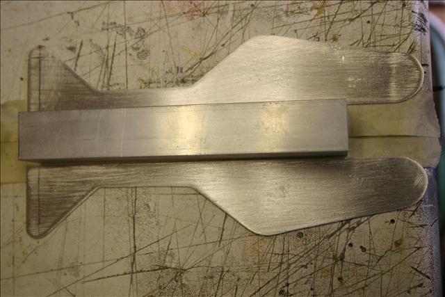
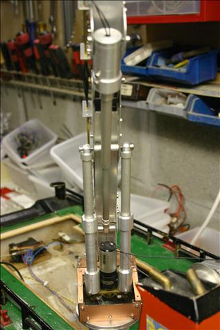
Solid arm:
The plates are glued to the square profile and after the glue was dried I mounted some screws for more strenght.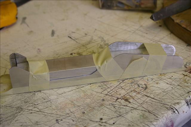
The side plates are glued to the profile.
The hinge hole in the side plates for the mounting of the cylinders.
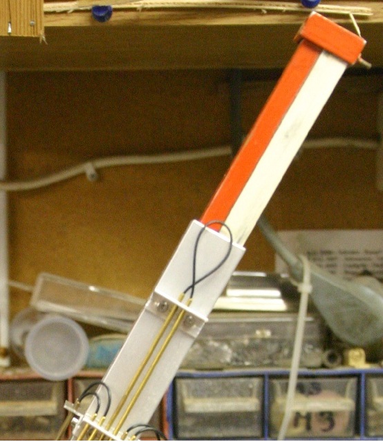
Bending arm:
The drive of the bending arm exist out of one cylinder. This one is build up out of three major parts: spindle, piston rod and the extrior cylinder. This is all so made that you don't see the threaded rod when the cylinder moves.
The motor is mounted directly on the threaded rod. The housing is made with aluminium on the lathe and made as small as possible.
Because the lack of space at the bottom hinge the motor is placed on the topside of the cylinder and also the housing is now part of the hinge.
Sliding:
The motor for the sliding arm is mounted inside the square profile of the bending arm, the drive for the arm is also a threaded rod. The sliding arm is from the original crane.
Turning:
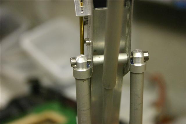
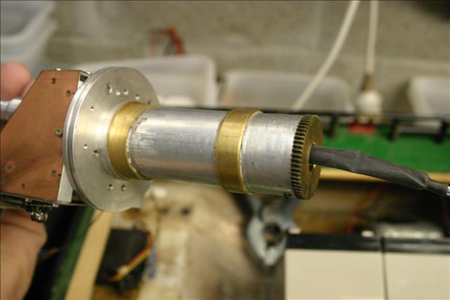
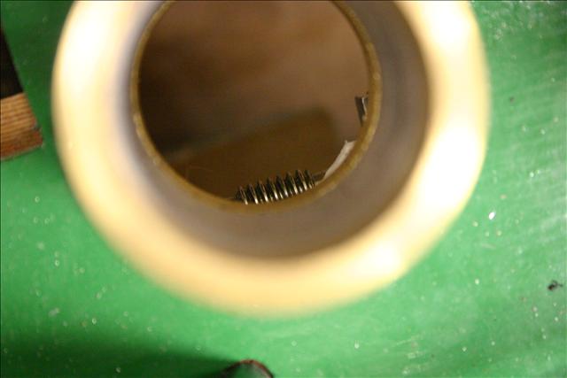
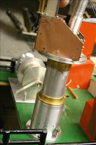
The turning is done through a wormgear that drives the crane. One gear is mounted inside the base tube of the crane..
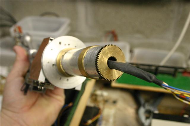
The base tube with the gear and two guiding rings made of brass.
The cables come through the gear.
The driven part of this wormgear is mounted underneath the deck.
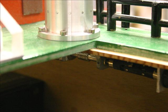
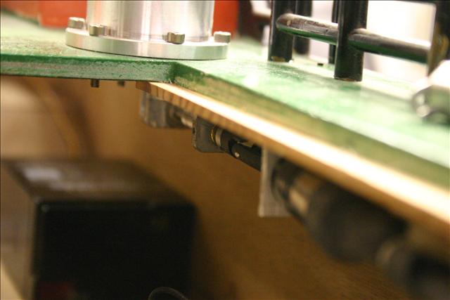
The wormgear is visible through the crane foot.
I cane remove the complete crane by lifting him out of the crane foot, mouting is just slide it into the foot and into the gears.
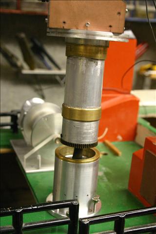
The base tube is ready to slide into the foot.
The gear and the first guiding ring are in the crane foot.
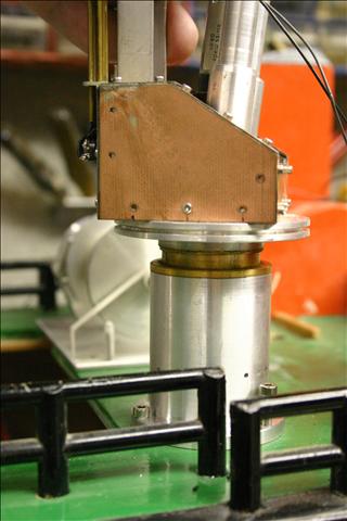
Almost completly inside the crane foot.
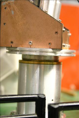
Completly down the foot.
Base / Motorhouse:
The crane is mounted on a turntable on wich the housing for the gears and hinges is build. As material I used 0.4 print board material and small L profiles. The plates are mounted with M1,6 screws to the profiles. On this way its getting a solid construction.
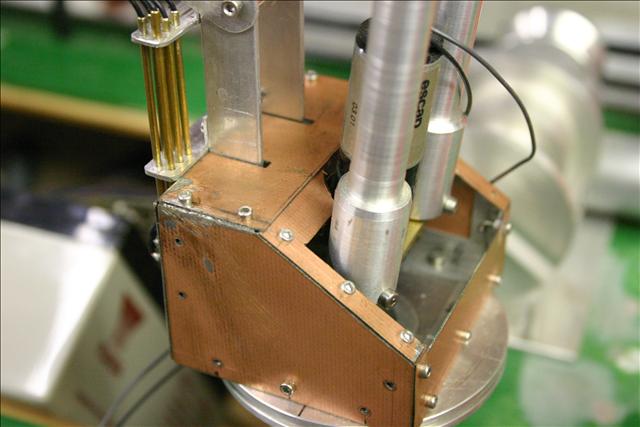
For maintenance I can remove the complete housing without removing any cylinders.
Finishing:
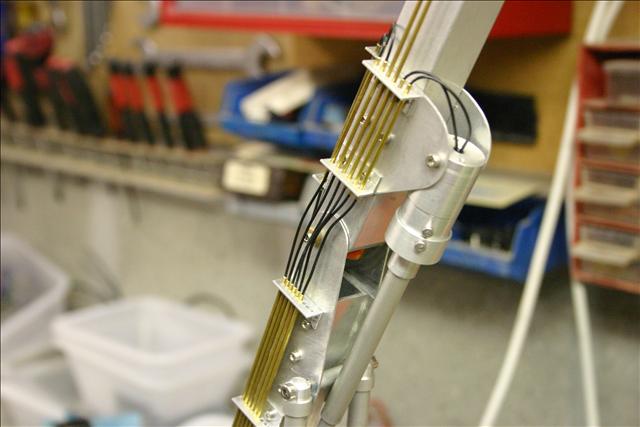
The electrical cables are neatly worked away inside imitation pluming and the cables are now the flexible connection, this gives a clean view of the crane.
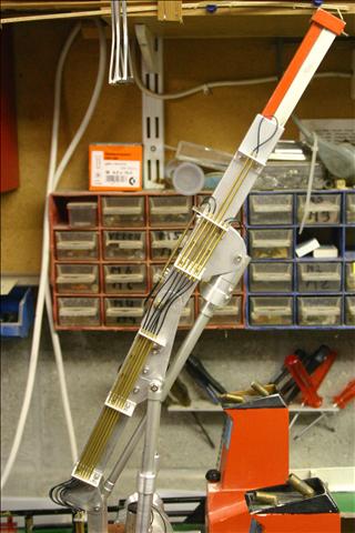
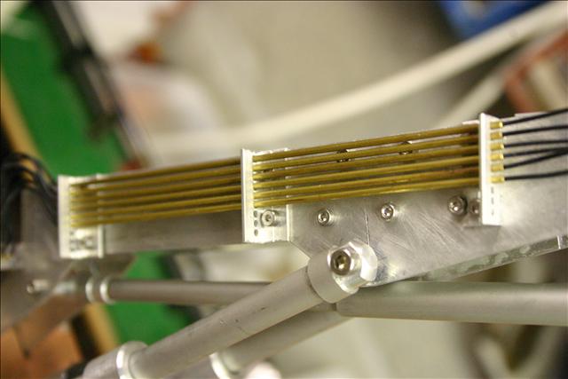
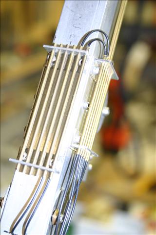
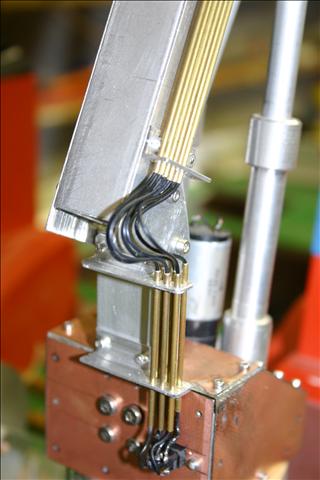
All this make it a lot more work because you have to make mounting brackets but its worth the extra effort. All the cables are connected to the housing by small printboard connectors. From these connectors the cables go through the base tube into the hull and there they will be connected to the switch module with a sub-D connector.
The video of the crane, still without the rc control.